
This page will probably always be under development, 55 revisions so far! I really welcome Your comments and ideas. Some subjects might be debatable. Mark what You want to comment and press Ctrl + Enter, to open a comment window privately to me, or use the comment box at the bottom of this page, for a public comment! The aim of the page is to clarify the most used terms, when discussing DRC and audio.
- Amplitude vs Frequency – Amp/F here for typical three-way loudspeaker.

- Magnitude = Amp/F is often used in the audio field, but Magnitude is also used with other meanings in other fields, Math = Size, Astronomy = Brightness, Geology = Energy, also there is no single word term for Pha/F anyhow. So I am going to use Amp/F and Pha/F, to be as clear as possible in this blog.
- Phase vs Frequency – Pha/F same loudspeaker as above. Mind You that to lower the size of plot, the “jumps” at 50, 500 and 3500Hz, really are not jumps, they continue “downwards” as, -180 is the same as +180 in phase…. I certainly would prefer a larger/taller continuous diagram, than these “false jumps”, for clarity of whats really going on. There are NO sudden 360 degrees shift!

- Frequency Response – FR is often used in the meaning of Amplitude vs Frequency, making the common but faulty assumption, that Phase vs Frequency is flat and non changing over the audible spectrum. Something a loudspeaker designer knows all to well is not true. So I will differentiate them as Amp/F and Pha/F from FR.
- Transient response – TR is really FR for a transient, both amplitude AND phase in one plot, but in this case over time, instead as over frequency. Impulse is another word for transient in this case.

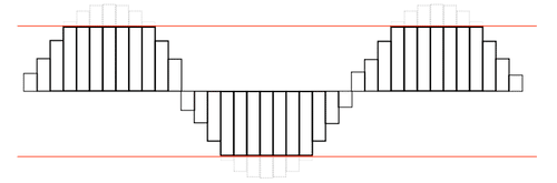
- Dirac pulse – Is a theoretical step pulse, like a square wave but with zero width. Mathematically always has the area 1, thus its height is infinite.
- Amplitude – the size/magnitude of a signal. Usually in Volts when expressed “absolute” or decibels when “relative”.

1/ is peak amplitude, 2/ is peak to peak 3/ is RMS (RootMeanSquare) amplitude
- Bandwidth – the range of frequencies used, is often 20Hz to 20kHz in HiFi-audio.
- Analog Clipping – distortion by cutting the peak of an analog signal. Typically in an amplifier when it reaches its amplification max limit.

Easily detected by human ear, as it produces “odd” harmonic distortion.- Compressor – a technique to limit the dynamics of a signal, i.e. low levels are amplified more than high levels. A tube or CMOS-amp, acts as a compressor when close to its max output producing “even” harmonic distortion.

- Digital Clipping – When a PCM signal reaches its max numerical value.
- Jitter – Distortion by means of time/speed variations of a digital signal, compare it with wow and flutter of an analog signal . USB and HDMI usually have more of it than You want as they seldomly use high quality clocks.
- WOW – Slow speed variations of an analog signal i.e. from a turntable or tapedeck.
- Flutter – Fast speed variations of an analog signal i.e. from a turntable or tapedeck.
- S/PDIF – Abb. of Sony/Philips Digital Interface Format. Standardized interface for digital audio signals. Can be electric coaxial RCA or optical Toslink. For two channel unkompressed PCM or up to 7.1 compressed (Like DTS). Can not carry Dolby TrueHD, nor DTS-HD Master Audio due to bandwidth limitations. Max resolution 20bits (24 optional). S/PDIF has the clocking built into the signal “word clock”, not an external clock. Thus some debate S/PDIF-jitter is NOT from the signal but from the decoding of the signal in the receiver.
- Toslink – Optical connector for S/PDIF
- HDMI – HighDefinitionMultimediaInterface is a proprietary combined digital audio/video interface. In version 1.4 and above, it can carry all audio of S/PDIF but also Dolby TrueHD and DTS-HD Master Audio. It does not have a separate audio clocking scheme, but relies solely on the receivers unpacking and clocking. Thus jitter can be high in bad implementations.
- USB – UniversalSerialBus its ver 2.0 and above can handle at least 480Mb/s more than adequate for all audio purposes. If NOT used in asynch mode it relies solely on the senders clock (might be a PC and not made for low jitter audio purposes)
- Group Delay- The group delay of a filter is a measurement of the average delay of the filter, as a function of frequency. It is the negative first derivative of a filter’s Pha/F.
- Harmonic Distortion – harmonics wrongly added by the HiFi equipment and the room.
- Impedance – dependent on frequency, it is the AC variant of resistance in DC. Here shown for a typical closed box loudspeaker.

- Oversampling – used in DAC systems, e.g. a CD-player to increase its signal frequency, making it easier to filter out unwanted signals, with less side effects.
- Phase – Refers to the timing relationship of two or more signals or soundwaves.
- Phase Coherence – the relationship and timing of sounds that comes from different drivers (subs, mids, tweets). When distance between ears and the drivers differs, they are out of coherence, which will produce phase distortion.
-
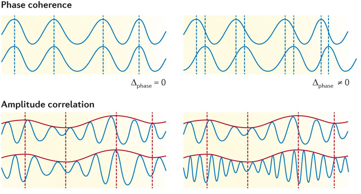
- Phase Distortion – a type of audible distortion caused by time delay between various parts of the signal, the result of phase being out of coherence.
- Near Field = measurement/listening so close to the speaker that reflections from the room can be neglected.
- Finite Impulse Response – FIR (finite as limited to end at some point in time) a FIR-filter is always stable as it has NO feedback of its output back to the filter (as opposed by IIR), easily implemented for linear phase, requires more computational power and more memory, especially when the sample rate is much higher, than the filterrange eg 192kHz of bit streamed audio files. One easily understood implementation of FIR would be “moving average”.
- Infinite Impulse Response – IIR (infinite as ongoing without end point in time) IIR-filter is not always stable, as it has feedback of its output to the filter and thus could thus inject “ringing”. It requires less memory and processor power, than FIR. It does not easily support linear phase. IIR filters can usually also be implemented in the analog domain.
- Minimum phase filters – A filter that has the shortest time delay for a given signal, thus it has the minimum phase change.
- Maximum phase filters – The opposite of the above, has no practical use in DRC.
- Mixed phase filters – explanation will follow later
- Linear phase filters has constant group delay – the filter adds some delay, but that delay is constant over all its frequencies.
- Crosstalk-cancellation – used when speakers are so close together, that the ears have difficulties to discriminate the left channel from the right.
It’s usually done by mixing in a little of the other channel in anti-phase. It’s what You had a button “wide” on Your portable stereo in the 80-ies for.
Then done by a special TI-chip, today done in SW in Your mobile phone, usually together with DRC (DSC) of the speakers as well. Dirac calls it Panorama Sound. - Bit – The smallest piece of digital info a “1” or a “0”
- Word – A bunch of bits, used to store a digital value, usually 8, 16,20,24 or 32 bits in the audio field. Its used either in “integer-format” or in “floating point-format” then with some bits of the word used for the integers and some for the exponent. The integer-format of a given word length giving more detail, but less dynamics than its counterpart.
- Byte– 8 bits, used to store a value digitally.
- Bits per second – bps
- Sampling Rate – S/s samples per second, usually expressed in Hz, is often a multiplier of 24kHz from 48 to 384kHz, except for the CD standard being 44.1kHz
- Digital Room Correction – DRC – here used as the concept of both DRC + DSC – but really JUST correction of the distortion introduced by the room
- Digital Speaker Correction – DSC – just correction of the distortion introduced by the speaker
- Digital Signal Processor – DSP, a special processor optimized for signals
- Central Processing Unit – CPU, the main processor of Your PC or mobile phone it can do DSP and GPU work but is slower at that.
- Graphics Processing Unit – GPU, a special processor optimized for graphics, common in todays PC´s and mobile phones
- Analog to Digital conversion – A/D
- Digital to Analog conversion – D/A
- PulseCodeModulation – PCM, a byte wide method, describing an analog signal in digital terms, usually 16 or 24 bits wide words in HiFi-audio. In this figure example word of 5 bits = 0 to 15, as discrete values.

- PulseDensityModulation – PDM, a one bit wide method, describing an analog signal in digital terms, used in DSD.

- BitStream – BS is a bit oriented method of describing an analog signal in digital terms as a stream of single bits
- DirectStreamDigital – DSD is a bit stream format, using PDM to describe the waveform of the sound.
- Streamed Audio – SA, a method of supplying material to the listener, NOT downloading the entire file, before playing it, could be in PCM or PDM.
- CompactDisc – CD, PCM 16 bits 44,1 kHz sampling rate
- BlueRayDisc – BRD, PCM up to 24 bits, up to 192 kHz. DVD-Audio has the same specs, same physical size as CD
- SuperAudioCompactDisc – SACD, disc format using DSD of 2,8224 MHz, same physical size as CD, often combined with CD recording format for compatibility
- MP3 – The most common format of audio files today. Patented with license fees. Destructive compression. PCM 16-bits. Abbreviation of MPEG-1 layer 3 (MovingPicturesExpertGroup).
- FLAC – Most common “HiFi-format” today. Non destructive compression. License free. PCM 16/20/24/32 bits max 384kHz Abb. of FreeLosslessAudioCodec
- ALAC – Apples non destructive, compression. License free. PCM 16/20/24/32 bits max 384kHz
- WAV – Microsoft non destructive, non compression. License free. PCM 16 bits max 44.1kHz (same as CD)
- SPL – Sound Pressure Level, measured i dB or deciBel, a logarithmic scale based on the lowest SPL a normal human can hear (0dB) a doubling i SPL equals +3dB
- PCM vs DSD – Most recording, mixing and after processing (like DRC, volume and tone control) is made in PCM. Recording mics in analog, converting to DSD for storage, converting to PCM for mixing, converting back to DSD for mastering, followed by converting to PCM for processing in the amplifier, finishing with D/A or PDM conversion before power amplification. Each conversion adding distortion. But the same goes for conversions within PCM (no amp or DRC vendor tells what format it does its processing in).
Best would of course be NO conversion at all, same format from the recording to the power amp. Does that exist at all today? I wonder what the min, avg and max number of conversions are?
Nice try to straighten out common misunderstandings and myths, thus setting the standard. Looking forward to see other sites using it as reference!
Much needed article! So much confusion about terminologi. Especially “frequency response” and abberviations well explained.
Terminology well setup. There are so many “buzzwords” in this business, that an explanation is dearly needed. Thanks!